Advertise type top bottom 500*100 Size
1month: only $5
1 year : only $13
3 year: only $33
payment only Alertpay.com .My Alertpay E-mail is umarhussain65@yahoo.com
Contact Me : make.bhai@yahoo.com
sent a detail of ad so iam guide you by E-mail.
Sunday, 2 October 2011
Saturday, 10 September 2011
3 Types Wind turbines
Wind turbines can rotate about either a horizontal or a vertical axis, the former being both older and more common.[13]The three primary types:VAWT Savonius, HAWT towered; VAWT Darrieus as they appear in operation.  Wind turbines can rotate about either a horizontal or a vertical axis, the former being both older and more common.[13]
Wind turbines can rotate about either a horizontal or a vertical axis, the former being both older and more common.[13]Horizontal axis

Components of a horizontal axis wind turbine (gearbox, rotor shaft and brake assembly) being lifted into position
Since a tower produces turbulence behind it, the turbine is usually positioned upwind of its supporting tower. Turbine blades are made stiff to prevent the blades from being pushed into the tower by high winds. Additionally, the blades are placed a considerable distance in front of the tower and are sometimes tilted forward into the wind a small amount.
Downwind machines have been built, despite the problem of turbulence (mast wake), because they don't need an additional mechanism for keeping them in line with the wind, and because in high winds the blades can be allowed to bend which reduces their swept area and thus their wind resistance. Since cyclical (that is repetitive) turbulence may lead to fatigue failures, most HAWTs are of upwind design.

11 x 7,5 MW E126 Estinnes Windfarm, Belgium, July 2010, one month before completion, with unique 2 part blades
Modern wind turbines

Turbine blade convoy passing through Edenfield in the UK
Turbine design and construction
 Wind turbines are designed to exploit the wind energy that exists at a location. Aerodynamic modeling is used to determine the optimum tower height, control systems, number of blades and blade shape.
Wind turbines convert wind energy to electricity for distribution. Conventional horizontal axis turbines can be divided into three components.
- The rotor component, which is approximately 20% of the wind turbine cost, includes the blades for converting wind energy to low speed rotational energy.
- The generator component, which is approximately 34% of the wind turbine cost, includes the electrical generator, the control electronics, and most likely a gearbox (e.g. planetary gearbox,[25] adjustable-speed drive [26] or continuously variable transmission[27]) component for converting the low speed incoming rotation to high speed rotation suitable for generating electricity.
- The structural support component, which is approximately 15% of the wind turbine cost, includes the tower and rotor yaw mechanism.[28]
Wednesday, 3 August 2011
Vertical-axis wind turbines Guide
 Vertical-axis wind turbines
Vertical-axis wind turbines (or VAWTs) have the main rotor shaft arranged vertically. Key advantages of this arrangement are that the turbine does not need to be pointed into the wind to be effective. This is an advantage on sites where the wind direction is highly variable, for example when integrated into buildings. The key disadvantages include the low rotational speed with the consequential higher torque and hence higher cost of the drive train, the inherently lower power coefficient, the 360 degree rotation of the aerofoil within the wind flow during each cycle and hence the highly dynamic loading on the blade, the pulsating torque generated by some rotor designs on the drive train, and the difficulty of modelling the wind flow accurately and hence the challenges of analysing and designing the rotor prior to fabricating a prototype.[citation needed] With a vertical axis, the generator and gearbox can be placed near the ground, using a direct drive from the rotor assembly to the ground-based gearbox, hence improving accessibility for maintenance.
When a turbine is mounted on a rooftop, the building generally redirects wind over the roof and this can double the wind speed at the turbine. If the height of the rooftop mounted turbine tower is approximately 50% of the building height, this is near the optimum for maximum wind energy and minimum wind turbulence. It should be borne in mind that wind speeds within the built environment are generally much lower than at exposed rural sites.[citation needed]
[edit] Subtypes
- Darrieus wind turbine
- "Eggbeater" turbines, or Darrieus turbines, were named after the French inventor, Georges Darrieus.[17] They have good efficiency, but produce large torque ripple and cyclical stress on the tower, which contributes to poor reliability. They also generally require some external power source, or an additional Savonius rotor to start turning, because the starting torque is very low. The torque ripple is reduced by using three or more blades which results in greater solidity of the rotor. Solidity is measured by blade area divided by the rotor area. Newer Darrieus type turbines are not held up by guy-wires but have an external superstructure connected to the top bearing.[citation needed]
- Giromill
 A subtype of Darrieus turbine with straight, as opposed to curved, blades. The cycloturbine variety has variable pitch to reduce the torque pulsation and is self-starting.[18] The advantages of variable pitch are: high starting torque; a wide, relatively flat torque curve; a lower blade speed ratio; a higher coefficient of performance; more efficient operation in turbulent winds; and a lower blade speed ratio which lowers blade bending stresses. Straight, V, or curved blades may be used.[citation needed]
- Savonius wind turbine
- These are drag-type devices with two (or more) scoops that are used in anemometers, Flettner vents (commonly seen on bus and van roofs), and in some high-reliability low-efficiency power turbines. They are always self-starting if there are at least three scoops.
- Twisted Savonius
- Twisted Savonius is a modified savonius, with long helical scoops to give a smooth torque, this is mostly used as roof windturbine or on some boats (like the Hornblower Hybrid).
vertical-axis wind turbines
 Today I was asked what is a ‘vertical-axis wind turbines‘. Good question if you think about it because without a picture it is hard to explain. It is a wind mill that points up but captures wind from the side, right? (that made me grin) See the picture here… kinda like that, but what is a vertical-axis wind turbine? A vertical-axis wind turbine is a type of wind turbine where the main rotor shaft is set vertically. Among the advantages of this arrangement are that generators and gearboxes can be placed close to the ground, and that VAWTs do not need to be pointed into the wind. Thus they are omni-directional or do not have to be pointed when the wind changes directions. This is really great for areas where the wind shifts directions often or is generally erradic in nature. The vertical-axis wind turbine seems to thrive in this type of environment.
Want to know more about vertical-axis wind turbines and the green energy they produce?
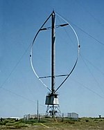
 Vertical axis wind turbine

The world's tallest vertical-axis wind turbine, in Cap-Chat, Quebec
Vertical-axis wind turbines (VAWTs) are a type of wind turbine where the main rotor shaft is set vertically and the main components are located at the base of the turbine. Among the advantages of this arrangement are that generators and gearboxes can be placed close to the ground, which makes these components easier to service and repair, and that VAWTs do not need to be pointed into the wind.[1] Major drawbacks for the early designs (Savonius, Darrieus and giromill) included the pulsatory torque that can be produced during each revolution and the huge bending moments on the blades. Later designs solved the torque issue by using the helical twist of the blades almost similar to Gorlov's water turbines.
A VAWT tipped sideways, with the axis perpendicular to the wind streamlines, functions similarly. A more general term that includes this option is "transverse axis wind turbine". For example, the original Darrieus patent [2], includes both options.
Drag-type VAWTs, such as the Savonius rotor, typically operate at lower tipspeed ratios than lift-based VAWTs such as Darrieus rotors and cycloturbines.
 [edit] General aerodynamics
The forces and the velocities acting in a Darrieus turbine are depicted in figure 1. The resultant velocity vector, , is the vectorial sum of the undisturbed upstream air velocity, , and the velocity vector of the advancing blade, .

Thus, the oncoming fluid velocity varies, the maximum is found for  and the minimum is found for
  , where θ is the azimuthal or orbital blade position. The angle of attack, α, is the angle between the oncoming air speed, W, and the blade's chord. The resultant airflow creates a varying, positive angle of attack to the blade in the upstream zone of the machine, switching sign in the downstream zone of the machine.
and the minimum is found for , where θ is the azimuthal or orbital blade position. The angle of attack, α, is the angle between the oncoming air speed, W, and the blade's chord. The resultant airflow creates a varying, positive angle of attack to the blade in the upstream zone of the machine, switching sign in the downstream zone of the machine.From geometrical considerations, the resultant airspeed flow and the angle of attack are calculated as follows:

 [3]
[3]where  is the tip speed ratio parameter.
is the tip speed ratio parameter.The resultant aerodynamic force is decomposed either in lift (F_L) - drag (D) components or normal (N) - tangential (T) components. The forces are considered acting at 1/4 chord from the leading edge (by convention), the pitching moment is determined to resolve the aerodynamic forces. The aeronautical terms lift and drag are, strictly speaking, forces across and along the approaching net relative airflow respectively. The tangential force is acting along the blade's velocity and, thus, pulling the blade around, and the normal force is acting radially, and, thus, is acting against the bearings. The lift and the drag force are useful when dealing with the aerodynamic behaviour around each blade, i.e. dynamic stall, boundary layer, etc; while when dealing with global performance, fatigue loads, etc., it is more convenient to have a normal-tangential frame. The lift and the drag coefficients are usually normalised by the dynamic pressure of the relative airflow, while the normal and the tangential coefficients are usually normalised by the dynamic pressure of undisturbed upstream fluid velocity.

A = Surface Area
The amount of power, P, that can be absorbed by a wind turbine.

Where Cp is the power coefficient, ρ is the density of the air, A is the swept area of the turbine, and ν is the wind speed.[4]
[edit] Advantages of vertical axis wind turbines
VAWTs offer a number of advantages over traditional horizontal-axis wind turbines (HAWTs). They can be packed closer together in wind farms, allowing more in a given space. This is not because they are smaller, but rather due to the slowing effect on the air that HAWTs have, forcing designers to separate them by ten times their width.[5] [6]
VAWTs are rugged, quiet, omni-directional, and they do not create as much stress on the support structure. They do not require as much wind to generate power, thus allowing them to be closer to the ground. By being closer to the ground they are easily maintained and can be installed on chimneys and similar tall structures.[7]
[edit] Disadvantages of vertical axis wind turbines
Some disadvantages that the VAWTs possess are that they have a tendency to stall under gusty winds. VAWTs have very low starting torque, as well as dynamic stability problems. The VAWTs are sensitive to off-design conditions and have a low installation height limiting to operation to lower wind speed environments.[8]
The blades of a VAWT are prone to fatigue as the blade spins around the central axis. The vertically oriented blades used in early models twisted and bent as they rotated in the wind. This caused the blades to flex and crack. Over time the blades broke apart and sometimes leading to catastrophic failure. Because of these problem, Vertical axis wind turbines have proven less reliable than horizontal-axis wind turbines (HAWTs).[9]
Research programmes (in 2011) have sought to overcome the inefficiencies associated with VAWTs by reconfiguration of turbine placement within wind farms. It is thought that, despite the lower wind-speed environment at low elevations, "the scaling of the physical forces involved predicts that [VAWT] wind farms can be built using less expensive materials, manufacturing processes, and maintenance than is possible with current wind turbines"
Small Wind Electric Systems
Small Wind Electric Systems
Small wind electric systems are one of the most cost-effective home-based renewable energy systems. These systems are also nonpolluting.
If a small wind electric system is right for you, it can do the following:
- Lower your electricity bills by 50%–90%
- Help you avoid the high costs of having utility power lines extended to a remote location
- Help uninterruptible power supplies ride through extended utility outages.
Small wind electric systems can also be used for a variety of other applications, including water pumping on farms and ranches.
Here you can find the following information:
How a Small Wind Electric System Works
Learn the basics of how a small wind system produces electricity.Evaluating a Potential Small Wind Turbine Site
Start here to determine whether a small wind energy system would be feasible, practical, and economical for you.Small Wind Electric System Components
Learn more about system components—turbines, towers, and balance-of-system parts.Installing and Maintaining a Small Electric Wind System
Find out what you need to consider before you install a system, including basic maintenance tips.
Build a solar heater
Build a solar heater
By: Gary Reysa (www.builditsolar.com) © Gary Resa 2005
After walking into our new workshop one December morning and finding the inside temperature to be a bone-chilling 10°F (-12°C), I decided that it was time for a heating system! Given the rising costs of propane and our environmental concerns about using nonrenewable fossil fuels, a solar solution seemed fitting. I reviewed many solar collector concepts, and finally decided to install a thermosiphon air collector on the south wall of the building. The concept is elegant and simple. A thermosiphon design uses only the buoyancy of heated air to circulate air through the collector, eliminating the cost, maintenance, and energy consumption of fans, sensors, and controllers commonly used in other collector designs. On a sunny day, in a cold climate like ours here in Bozeman, Montana, this simple system can produce the heat equivalent of burning about 2 gallons (8 l) of propane. To minimize material use, I integrated the collector within the building’s structure. I also tried to make the collector easy to construct using readily available materials. In fact, making this collector should only take one trip to the hardware store and US$350. Set aside two or three days to complete the project.
Materials used to construct the thermosiphon collector can be found at most lumberyards and hardware stores.
The collector is 20 feet wide by 8 feet high (6.1 x 2.4 m) for an overall area of 160 square feet (15 m2). The collector is 6 inches (15 cm) deep. In most cases, make the collector as large as your south wall allows (see sizing solar collector). The top vent and bottom vent areas should each be at least 50 percent of the collector’s horizontal cross-sectional area (again, more is better). The collector frame is constructed from wood, and consists of six vertical members, a bottom sill, and a top sill. The six vertical 2 by 6s divide the collector into five, 4-footwide (1.2 m) bays. A 2 by 6 is used for the bottom sill. A 2 by 8 is used for the top sill, which should be sloped at about 10 degrees to shed rain. The collector frame attaches to the building by lag bolts from the inside. The collector is glazed with clear Suntuf corrugated polycarbonate panels. These panels have an ultraviolet light-resistant coating on their sun-facing side to extend their life. Each panel is 26 inches (66 cm) wide by 96 inches (244 cm) high. There are ten panels. Pairs of 26-inch-wide panels are joined over a 1- by 1-inch (2.5 x 2.5 cm) vertical wood strip to make the 4-foot-wide panels for each bay. Two, 1- by 1-inch horizontal members provide additional support for the glazing. The absorber is installed on battens placed about halfway between the glazing and siding. After measuring the thermal performance with one, two, and three layers of window screening, I found that two layers work best.
Disclaimer: Please use caution when working with tools such as saws, hammers, electric drills, etc.... Just because we feature these alternative energy how-to's does not directly imply that you will be able to do everything with any incident just by following the directions. Please make safety your number one concern! EnergyRefuge.com assumes no liabilities for accidents involving our instructions or those that are re-posted. Please use common sense and please consult a professional if needed.
After walking into our new workshop one December morning and finding the inside temperature to be a bone-chilling 10°F (-12°C), I decided that it was time for a heating system! Given the rising costs of propane and our environmental concerns about using nonrenewable fossil fuels, a solar solution seemed fitting. I reviewed many solar collector concepts, and finally decided to install a thermosiphon air collector on the south wall of the building. The concept is elegant and simple. A thermosiphon design uses only the buoyancy of heated air to circulate air through the collector, eliminating the cost, maintenance, and energy consumption of fans, sensors, and controllers commonly used in other collector designs. On a sunny day, in a cold climate like ours here in Bozeman, Montana, this simple system can produce the heat equivalent of burning about 2 gallons (8 l) of propane. To minimize material use, I integrated the collector within the building’s structure. I also tried to make the collector easy to construct using readily available materials. In fact, making this collector should only take one trip to the hardware store and US$350. Set aside two or three days to complete the project.
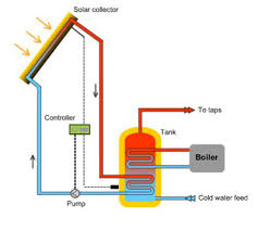
How It Works
The thermosiphon collector consists of clear, corrugated poly carbonate panels fastened to vertical 2 by 6s. The clear panels, on the building’s south face, admit sunlight. An absorber—in this case, two layers of black metal window screen—suspended inside the collector captures the sun’s
heat energy. The air around the mesh expands and rises as it warms, creating a convection current. Vents located at the top and bottom of the collector allow air to circulate and become heated. Cool air enters the lower vent, is heated by the absorber, and rises through to the upper vents that exit into the building’s interior. This circulation of air continues as long as the sun shines on the collector. At night, as air in the collector cools to outside temperatures, airflow tries to reverse. Air in the collector sinks through the bottom vents and attempts to pull the warmed air from the building through the top vents. Use of flapper valves on the top vents helps prevent this reverse circulation and keeps the heat inside.
Nuts & BoltsThe thermosiphon collector consists of clear, corrugated poly carbonate panels fastened to vertical 2 by 6s. The clear panels, on the building’s south face, admit sunlight. An absorber—in this case, two layers of black metal window screen—suspended inside the collector captures the sun’s
heat energy. The air around the mesh expands and rises as it warms, creating a convection current. Vents located at the top and bottom of the collector allow air to circulate and become heated. Cool air enters the lower vent, is heated by the absorber, and rises through to the upper vents that exit into the building’s interior. This circulation of air continues as long as the sun shines on the collector. At night, as air in the collector cools to outside temperatures, airflow tries to reverse. Air in the collector sinks through the bottom vents and attempts to pull the warmed air from the building through the top vents. Use of flapper valves on the top vents helps prevent this reverse circulation and keeps the heat inside.
The collector is 20 feet wide by 8 feet high (6.1 x 2.4 m) for an overall area of 160 square feet (15 m2). The collector is 6 inches (15 cm) deep. In most cases, make the collector as large as your south wall allows (see sizing solar collector). The top vent and bottom vent areas should each be at least 50 percent of the collector’s horizontal cross-sectional area (again, more is better). The collector frame is constructed from wood, and consists of six vertical members, a bottom sill, and a top sill. The six vertical 2 by 6s divide the collector into five, 4-footwide (1.2 m) bays. A 2 by 6 is used for the bottom sill. A 2 by 8 is used for the top sill, which should be sloped at about 10 degrees to shed rain. The collector frame attaches to the building by lag bolts from the inside. The collector is glazed with clear Suntuf corrugated polycarbonate panels. These panels have an ultraviolet light-resistant coating on their sun-facing side to extend their life. Each panel is 26 inches (66 cm) wide by 96 inches (244 cm) high. There are ten panels. Pairs of 26-inch-wide panels are joined over a 1- by 1-inch (2.5 x 2.5 cm) vertical wood strip to make the 4-foot-wide panels for each bay. Two, 1- by 1-inch horizontal members provide additional support for the glazing. The absorber is installed on battens placed about halfway between the glazing and siding. After measuring the thermal performance with one, two, and three layers of window screening, I found that two layers work best.
Next
Disclaimer: Please use caution when working with tools such as saws, hammers, electric drills, etc.... Just because we feature these alternative energy how-to's does not directly imply that you will be able to do everything with any incident just by following the directions. Please make safety your number one concern! EnergyRefuge.com assumes no liabilities for accidents involving our instructions or those that are re-posted. Please use common sense and please consult a professional if needed.
Solar DIY/How-Tos
Small Solar Electric Systems
 Small Solar Electric Systems
PV small solar electric systems are designed to harness solar power as it hits the earth. These are crystalline silicon panels that capture sunlight and turn it into electricity, which is then stored in a battery bank. When battery charges drop below a certain level, the solar panels recharge the batteries. Photovoltaic panels can be mounted on a rooftop or a freestanding solar array rack.
Energy Savers recommends that before buying a small solar electric system the buyer should be sure that the site where it will be installed has enough solar energy to meet the electricity needs of the building, both efficiently and economically. The supplier can perform an analysis or give instructions on how to do that. It’s important to consider the geographic orientation and the tilt of the solar panels as these can affect performance. Still according to Energy Savers, it’s also important to accurately size the components of these small solar systems, especially when these are not connected to the grid (“stand alone”). The organization advises considering how much of the total electricity need the PV system would be expected to supply, which can be done by analyzing past electricity bills and consulting with a potential provider of small solar electric systems. Before installing small solar electrical systems, it is necessary to obtain permits from the city or county’s building department (a building or electrical permit, or both). The PV provider often looks after this for the client, but it’s important to make sure that permitting costs and responsibilities are addressed when negotiating an electricity system. Those who live in a homeowners association must also get approval from them, unless state laws say that citizens have the right to install a small solar system on the home. The fact is that the number of these types of systems is growing. Even a cold weather state like Minnesota has been registering record numbers of solar system installations (178 between January and November 2010), thanks to governmental incentives that have reduced costs per watt to $7.50.
Are You Ready to Build Your Own Wind Turbine?
Are You Ready to Build Your Own Wind Turbine?
 Have you reached the point at which it would make sense to build your own wind turbine? If so, you’re definitely not alone!
We share a world in which the price of electricity is rising almost as quickly as the economic and job markets have crashed, leaving millions of homeowners desperate for ways to shave their monthly fuel bills. Switching to energy efficient appliances and light bulbs is a step in the right direction, but it’s only a baby step.
By deciding to build your own wind turbine, you’ll not only have a free and reliable energy source; you may even be able to sell the electricity you don’t use back to your electric company! You’ll also be protecting the environment and playing a small role in preventing climate change, because wind energy is clean energy. But what does it take to build your own wind turbine?
If the wind turbine you’re picturing stands a hundred feet tall with blades which would dwarf those on the propellers of the Titanic, relax. Not all home wind turbines are like the ones on utility company wind farms. They range in size from micro and pole-mounted models to those very tall stand-alone towers, and the sort of wind turbine you choose to build will depend largely on your location.
If your home is in an area surrounded by large buildings, the reality is that your local wind patterns probably won’t be regular enough for your wind turbine to generate more electricity than you’ll use in your own home. In that case, an inexpensive micro generator will be adequate. Using a micro wind turbine kit is the cheapest and easiest way to get the job done, but there are two caveats:
In an article, Discovery Channel News says that makers of some wind turbine kits might exaggerate the amount of electricity their products will produce in densely populated areas. Some of them, for instance, test their wind turbines on sea-level buildings in open areas when measuring the amount of watts of electricity they will produce at different wind speeds.
Some makers of wind turbine kits also claim their products will run silently and vibration-free. No wind turbine is either completely silent or completely still when the wind is blowing! So do your homework before choosing a micro wind turbine kit, and keep your expectations about the amounts of electricity you’ll be able to generate realistic.
 But what if you have enough open land that deciding to build your own wind turbine on a tower? According to The Owner's Guide to Energy Independence Alternative Power Sources for the Average American, most homeowners who have installed residential wind turbines have placed their generators on towers at least in height. Principles of physics dictate that speed at which air moves decreases as it is closer to the ground, with the greatest increase in speed occurring between ground level and sixty feet.
The wind turbine you build will have three blades resembling airplane propellers, which are connected to a magnetic generator, which in turn creates electricity. As the wind speed increases, the rotors to which your three blades are attached will turn more quickly, and the higher they are from the ground, the stronger the wind turning them will be so the more electricity they will make.
You can also, if you decide to build your own wind turbine, increase the amount of electricity generates by increasing the size of its blades. The design of the wind turbine you build should ensure that will automatically turn sideways in extremely high winds. This will allow the plane of the blades, which is normally perpendicular to the access of the turbine, to change and reduce the amount of wind load it experiences.
If you live in an exceptionally windy area, your home wind turbine should either be attached to a collection of batteries, or to your local power grid. Batteries will enable you to store the excess power you generate for days when there is little wind. Being connected to the power gird means you can sell it to your electrical utility.
Finally, while installing a micro or rooftop wind turbine may be something you can handle either by yourself or with the help of a few friends, erecting a 60-foot (or higher) tower weighing several tons will require the help of professionals.
Also, the Homeowner's Guide to Energy Independence suggests that you set aside 1% of the total cost of installing your home wind turbine for yearly maintenance expenses. Maintenance should include an annual inspection by the people who installed your wind turbine system, who will go over it from the ground up looking for possible problems!
If you really want to build your own wind turbine, and understand what’s involved, the opportunities have never been better!
How to build your own wind turbine - Aeolos Wind Turbine LLC
How to build your own wind turbine - Aeolos Wind Turbine LLC
With the development of renewable energy, more and more people are interested in DIY wind turbine. How to build your own wind turbine for home? There were some articles about how to build a DIY wind turbine however most of them are not easy to do or the DIY wind turbine is very simple.
Aeolos wind turbine tell you how to build your own excellent wind turbine. Firstly, you should know how many parts are in a small wind turbine?
Blades:
You can buy from your local hardware shop or the blade manufacturers. There are several materials of blades: Glass fiber, Aluminum alloy or alloy steel. At present, glass fiber blade is the most popular for small wind turbines.
Generator:
 Generator is the heart of a wind turbine. An efficient and good quality generator is most important for a DIY wind turbine. The following picture is the permanent magnetic generator of Aeolos wind turbine.
Turbine parts:
Other turbine parts included rotor, hub, bearing, gear, yaw and other parts. You can order these parts from the internet.
Control system:
The control system usually covered the control system and safety system. An automatic brake system is necessary. It is better to set a mechanical hand brake.
Tower:
There are three types of wind turbine tower now (Guyed tower, Lattice tower, Monopole tower). The height of tower and which type you should choose depended on you local site and wind speed.
Some useful resources about how to build your own wind turbine.
How does my wind generator work?
How does my wind generator work?
Every wind generator, whether they produce enough energy to power a city or to power a small radio, works on these same basic principles...- 1. The wind blows
- 2. The generator's vane (tail) causes it to turn into the wind
- 3. Blades attached to an alternator/generator experience the force of lift and begin to spin
- 4. The spinning creates electricity for us to use directly or to charge batteries
Sounds pretty simple eh? Well, then how the heck do I build one? Read on...
Tools Required
Surprisingly, building a simple wind generator only requires very basic hand tools, and if you are desperate you won't necessarily need all of them. I used...- Jigsaw (or a hacksaw and a lot of determination)
- Drill
- (2) Drill Bits (1/2", 7/32")
- Tape Measure
- Crescent Wrench
- Pipe Wrench
- Protractor (to measure angles for the hub)
- Sandpaper (various grits)
Parts Required
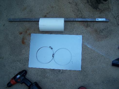
I wanted to be as minimal as possible with my design (I'm poor), so I took the already simple designs from around the web and made them even simpler. All of the parts are available at any local home improvement or hardware store, and the entire setup can be constructed in as little as a weekend. Many of the parts you may already have lying around, and lots of substitutions can be made (instead of 1" steel pipe for the tower, you could use an antenna pole for instance). Here are the parts I used to build my generator...- 10" x 14" Steel Sheet
- 10" x 1/4" Steel Nipple
- 1-1/4" Floor Flange
- 36" x 1" Square Tubing
- 1/2" Bore Circular Sawblade (for hub)
- 5/8" x 1/2" Arbor (to attach sawblade to motor shaft)
- (2) Metal Straps
- 8" x 4" PVC Pipe
- 30" x 8" PVC Pipe (6" pipe works well too)
- A DC Permanent Magnet Motor (preferably Ametek 30V or 260V 5A treadmill motor)
- (8) 1/4" Bolts (with washers and nuts)
- (2) 1/4" Sheet Metal Screws
- 10-40 Amp Diode (the bigger the better)
All of the above parts (with the exception of the motor), can be picked up in a single stop to any large hardware or home improvement store. For the motor, the most popular types are old tape drive motors manufactured by a company called Ametek. The key is to finding a motor that puts out the highest voltage per RPM. For instance, the Ametek I'm using is rated for 30V at 325 RPM, making it excellent as an electricity generator (for a nice output comparison of the Ametek motors commonly found on eBay and other sites see TLG Windpower). However, pretty much any permanent magnet motor with a good volt/RPM ratio will do. Keep in mind that if you want to generate useful electricity, you will need to produce at least 12V to charge deep cycle batteries or run an inverter. My setup can easily achieve 300-400 RPM in a pretty average wind (for Oklahoma). These instructions assume an Ametek motor with a 5/8" shaft, but can easily be adapted to other motors (search ebay for "wind generator" and you will get a listing of lots of good motors).
Blade Construction
Arguably, the most important part of a wind generator are its blades. A lot of people like to carve their own blades out of wood or composite materials. However, for the rest of us, it's quite easy to make a good set of generator blades from common PVC pipe (and the efficiency isn't too bad either). A 2-3 foot section of either 6" or 8" PVC pipe will do the trick. Before we go any further, here are a few blade theory quickies...- The longer your blades are the more "swept area" you have to gather energy from and easier your blades will spin in low winds, but the slower your rotation speed will be
- The tips of the blades always spin faster than the base, therefore one needs to take into account the "tip speed ratio" (TSR) when designing blades (there is a reason why old farm windmills will spin all year long at 40RPM)
- The power that can be extracted from the wind increases by the cube of wind speed (something like P=k*v^3 k=constant of wind generator, v=wind velocity)
- According to the Betz Limit, only about 59.3% of power can be extracted from the wind (so in reality P=.593*k*v^3, assuming k accounts for mechanical inefficiencies in the generator motor)
- The higher you get the generator off of the ground, the more wind it will be exposed to (the general recommendation seems to be 25-50ft., but I've had decent results at just 12ft.)
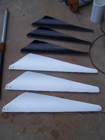
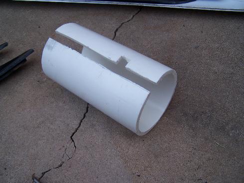
Cutting the blades for this machine is very simple. You will need to cut your PVC pipe into 3 sections, two 150 degree sections and one 60 degree section (I've attempted to illustrate this VERY APPROXIMATELY in my favorite CAD program--and by CAD program I really mean MS Paint). The red lines are cut marks. You will want to use a good tape measure and possibly some construction paper or newspaper to mark everything before you cut. The 150 degree angles will result in wide blades that start up in lower wind speeds, however this will lower the shaft turning speeds. In practice, you will find that the optimum angle could be anywhere from 75-150 degrees. The best idea is start out with a wide set of blades that you can always thin out later if you need to. Remember, measure twice and cut once!

After the blades are cut, I like to go ahead and smooth out all of the edges. If you want to follow aerodynamic theory, you can round the angled (leading) edge and flatten the straight (trailing) edge, but in practice I haven't seen this make much difference with PVC blades. So, you should end up with something roughly like these...
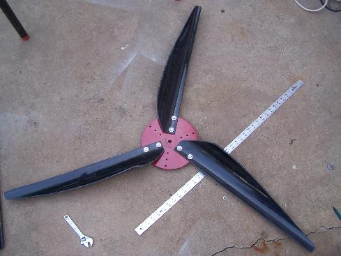
Hub & Blade Assembly
The next obstacle is building a hub to attach the blades to. There are many types of ways that this can be done. I have used circular sawblades and scrap steel disks. I recommend the sawblade approach, as they are readily available and easy to drill through. You can pick up an arbor with a 5/8" or 1/2" shaft at any homestore that will attach directly to the sawblade. Using the 1/4" drill bit, you will want to drill 3 sets of 2 holes 1" apart which each set 120 degrees from the next (this is where the protractor comes in handy, unless of course you are a Euclidean purist in which case you probably don't need a protractor). Here is a picture to make it more clear... | It's a pretty simple idea, but circular sawblades have worked out very well for me as hubs. Be sure and get some sort of rubber covering for the tooth edges and/or file down the edges as best you can, because the last thing you want is a hub of death flying at you if your generator decides to rip apart! |
Tail & Pivot Assembly
Now we need to build a spinning platform for our generator motor to rest on. To achieve this, we will use some square tubing, a pipe nipple, flange, and small sheet of steel. Here is my "CAD" draft of what I wanted my tail & pivot assembly to look like, and a real picture of some of the parts I used...
First, I recommend cutting the sheet steel with a jigsaw into a nice design for the the tail (Note: this step is quite unneccessary and ONLY for aesthethic reasons).
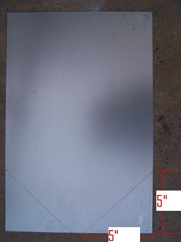
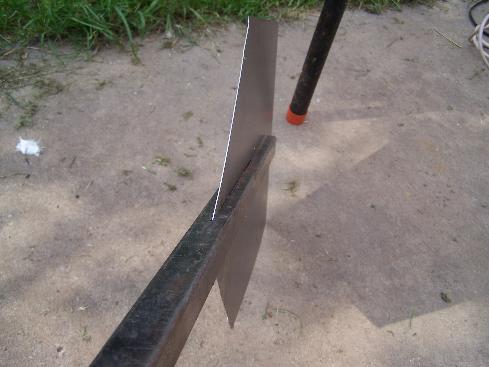
We then want to make a cut down the center of the square tubing. The length of the cut isn't that important, but I recommend about a 9" cut (this will help make balancing easier later on). We may then slide the tail metal into the hole and use the 1/4" drill bit to drill and attach the tail to the square tubing.
We will then want to cut out a weather covering for our motor. A piece of 4" PVC slips perfectly over the Ametek 30V motor that I use. I cut it out like so (note the side hole for the motor wires).
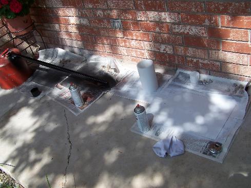
Then we go ahead and paint it all up to seal everything from the elements. I wouldn't recommend painting on your front porch like I did though...
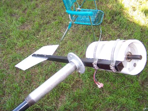
After everything is painted, we can now put it all together. Take the floor flange and put it under the square tubing about 6"-7" from the head. Mark the holes and drill them out with the 7/32" drill bit (or any bit close to but smaller than 1/4"). Attach with the 1/4" sheet metal screws. Use the metal straps to secure the motor and cover assembly, screw on the pipe nipple and you should have something like this...
Tower Assembly
Every wind generator needs a tower. I built mine from some pipe fittings from my local hardware store. If you already have an antenna pole or electrical conduit lying around, then you can skip this section. Here is my recommended parts list for a small extensible tower...- (2) 5' Sections 1" Pipe
- (1) 1" Pipe Coupling
- (3) 1" Pipe Elbows
- (4) 18" Pipe Sections
- (2) 12" Pipe Sections
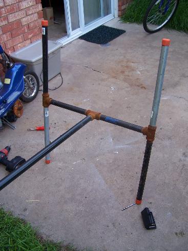
The tower base is pretty self-explanatory. Just hook up the elbows and pipe sections to create a base similar to this...
From there we can attach the 2 5' sections of pipe together to form a nice strong mini-tower for our generator to sit atop...
Finished Product
Now we are ready to attach the blades to the motor shaft with the arbor. You will also want to go ahead and attach some wire to the motor and run it to a device to power or a bank of batteries etc...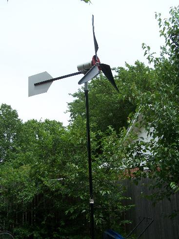
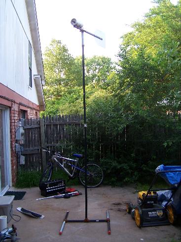
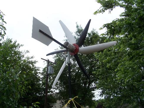
Here is a picture of the experimental design using six blades. It would spin in practically no wind, but would never get past 100RPM. At least it looked interesting!
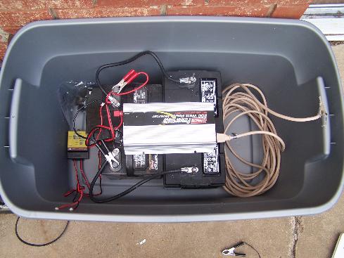
Here is the battery bank I'm feeding into in parallel with solar panels. I am just using two 12V marine deep cycle batteries that can be found at any place that sells car batteries. I keep them in a standard plastic tub with a hole cut in the sides for 12V fans I cannibalized from a couple of old Mac G4s (not pictured). Be sure and put a diode between the battery and the generator so that current doesn't flow from the battery to the motor.
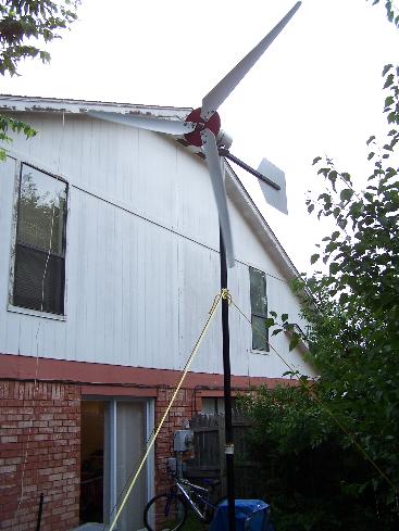
It turns out, cutting the blades a little thinner works better for my area. So I used the large white blades from the previous picture and thinned them out a bit. This resulted in the fastest shaft speeds as seen in first video at the top of this page.
Thank You


